Purpose
To learn how to set up electromyography (EMG) recordings for TMS and troubleshoot problems with biological and electrical noise because noise issues can prevent MEP status determination and lead to unusable TMS data.
Videos demonstrating how to identify the ECR and FDI muscles, how to perform skin preparation, and how to check for electrical impedance can be found on the EMG and TMS Training Videos page.
Overview
It is important to obtain good quality EMG traces that are free from noise issues because noise can make it harder, or impossible, to detect MEPs and lead to an incorrect MEP status determination. If MEP status cannot be determined due to noise issues then the VERIFY patient cannot be included in the primary study analyses.
Obtaining good quality EMG recordings involves several key steps, described below.
Ensure the EMG parameters are correct
Set up the equipment so the EMG recording is triggered by the TMS unit. The trigger should occur at 0 ms and you should be able to see the EMG trace before and after the trigger. Ideally the EMG trace begins at least 20 ms prior to the TMS stimulus and ends at least 50 ms after the TMS stimulus.
If you are using the MEGA-TMS system these settings will be already set up for you so you don’t need to change anything.
Securely position surface EMG electrodes in a standardized way
Prepare the skin over the muscles of interest with the following steps to improve the quality of the EMG traces:
- Locate where you’ll be placing the electrodes on the participant, and steps for doing this are provided below. Electrodes should not be placed over areas of broken skin.
- Shave to remove any hair over the areas the electrodes will be placed
- Clean the skin with an alcohol wipe
- Lightly abrade the skin with prep tape or an electrode gel
- Position the electrode so the center is on the skin you have prepared
- Securely stick the electrode to the skin and tape them down if needed to ensure good contact with the skin
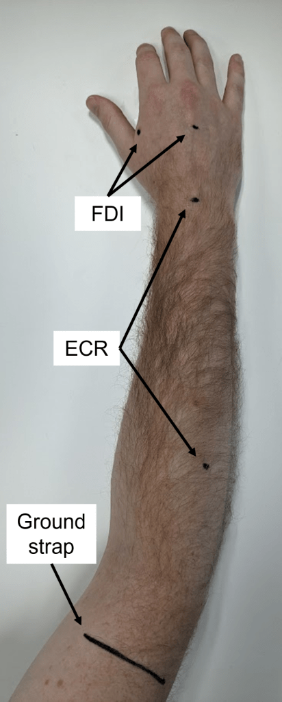
Extensor Carpi Radialis (ECR) is a muscle located in the posterior compartment of the forearm and it’s predominant role is to extend the wrist. Electrode placement for the ECR:
- Put one electrode over the muscle belly
- Put the second electrode over the dorsal surface of the wrist, centered between the radial and ulnar styloid processes.
To help identify the ECR muscle belly and isolate it from the extensor digitorum muscle belly you can ask the patient to extend their wrist with their fist closed if they are able. By palpating the participant’s forearm while they extend their wrist in the approximate area where the electrode will be placed as indicated in the picture on the right you will feel the ECR muscle belly. If the patient is unable to extend their wrist then the ECR muscle belly can be found by palpating the large brachioradialis muscle belly that runs along the radial (lateral) border of the forearm, and then rolling your fingers off to the extensors, which should lead to palpating the ECR muscle belly. The ECR muscle belly should be along an imaginary line running from the lateral epicondyle of the humerus to the styloid process of the radius.
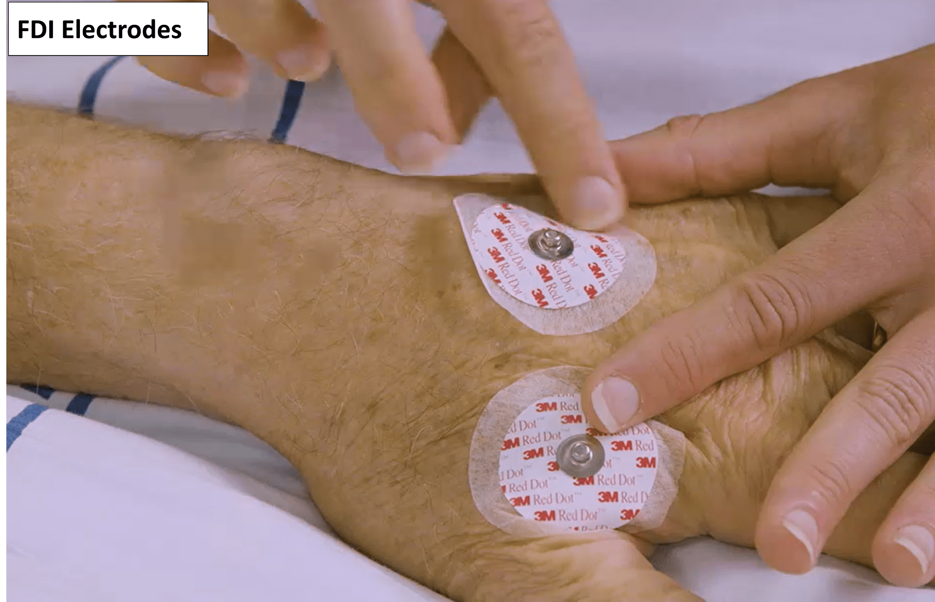
First Dorsal Interosseous (FDI) is a muscle in the hand that primarily acts to abduct the index finger. Electrode placement for the FDI:
- Put one electrode over the muscle belly
- Put the second electrode in the center of the dorsum of the hand.
The FDI muscle body is located slightly proximal to the webbed space between the thumb and index finger on the dorsal side of the hand. It is the thicker, fleshy part of the web between the thumb and index finger, and can be palpated by having the patient abduct their index finger if possible. Make sure the electrode is placed over the muscle belly and not the webbed space between the thumb and index finger.
In addition to the ECR and FDI electrodes you will also need a ground strap or electrode, and both of them should work equally as well. If you are using a MEGA-TMS system you should be using the ground strap that came with the stimulator.
- If you are using a ground electrode then it should be positioned over a bony prominence such as the dorsum of the hand or the lateral epicondyle of the humerus.
- If you’re using a ground strap then it should be placed around the arm just proximal to the elbow. The ground strap has to be placed against the participant’s skin and not on top of clothing. The metal pin should be visible and facing outwards.
Securely connect the electrodes to the EMG unit
Connect the electrodes to the EMG unit via cables, ensuring they are securely attached at both ends. If you are using a MEGA-TMS system pictures about how the cables should attach to the EMG unit can be found here.
Channel 1 should be connected to the ECR
Channel 2 should be connected to the FDI
Once you have connected the electrodes to the EMG unit you are ready to start stimulating the participant which will be covered in module 4. The rest of this module will teach you how to identify different types of noise and how to troubleshoot them.
Noise-Free EMG Traces
When the EMG is noise-free it will appear a as a flat line, with the only potential deflections being an MEP and the stimulus artefact. The stimulus artefact is generated by the firing of the TMS coil and only causes issues if it is prolonged as described towards the end of this module.
Below are some examples of EMG traces that are free from noise issues. This is what you should be aiming for with your own EMG traces.
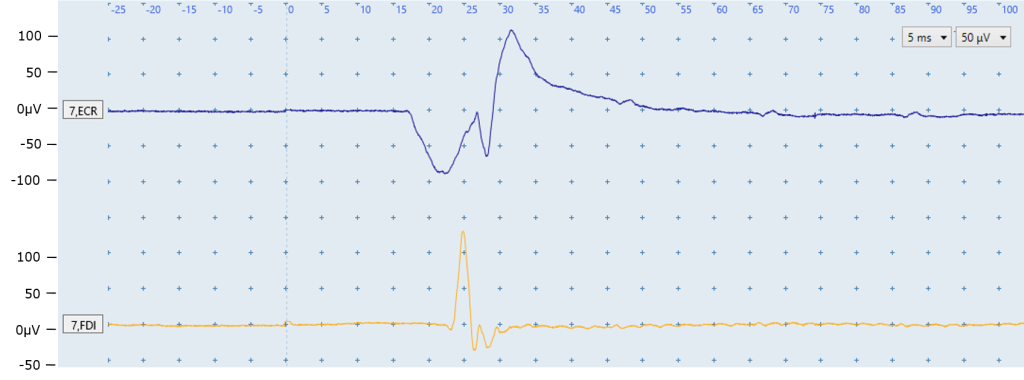
Figure A: In the above image you can see the ECR (top) and FDI (bottom) EMG traces are flat with no noise present. The only deflections are the MEPs in the ECR and FDI traces.

Figure B: Both EMG traces in the above image are free from noise issues, and no MEPs are present. You can see a slight deviation at 0ms in the FDI trace caused by the stimulus.
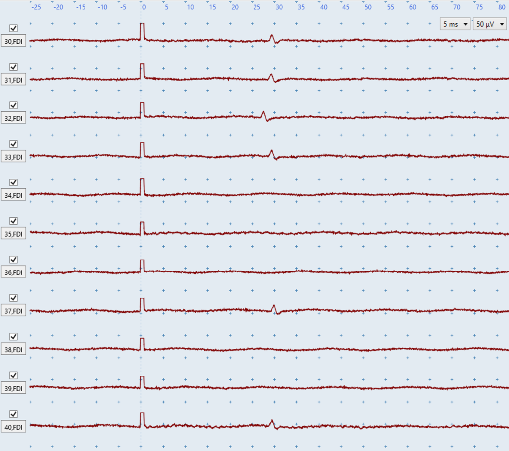
Figure C: The above image shows numerous FDI traces in a row. You can see very small FDI MEPs in several traces with amplitudes of ~20 microvolts. These MEPs could only be detected because the EMG is free from noise because even a small amount of biological or non-biological noise would obscure these MEPs and could lead to an incorrect MEP status determination.
There are numerous types of noise that can affect EMG traces, and they are broadly defined as being either biological or non-biological noise. The first step to troubleshooting any noise is to determine whether it is biological or non-biological although both can be present at the same time. The below sections will cover the following types of noise:
| Biological noise | Non-biological noise |
|
|
Biological Noise
You need to check the EMG signal is free of biological noise. There are two main sources of biological noise: muscle activation and sporadic motor units firing.
Muscle activation
Muscle activation means the ECR and/or FDI are active when stimulation occurs as the participant is not completely at rest. Muscle activation interferes with the quality of EMG traces and make it difficult to identify MEPs, which is why you should aim to have your participants upper limbs completely relaxed and at rest during TMS. This is most easily guaranteed by having your participant rest their hand on a pillow in their lap while you stimulate them such as in the picture on the right.
You will need to monitor the EMG signal throughout each session and try to eliminate any noise that arises due to muscle activation. If the patient is performing bilateral facilitation then muscle activation is expected in the EMG traces and should not be troubleshooted.
The key feature to distinguish muscle activation from non-biological noise is that muscle activation noise does not have a regular pattern in the EMG trace, as you can see in the examples below.

Figure D: The ECR muscle EMG trace (top) displays biological noise because the ECR is activated. The noise in the ECR trace can be identified as muscle activation because it does not have a regular pattern. No MEP is present in the ECR trace. No noise problems are present in the FDI muscle EMG trace. Although the stimulus artefact at 0ms in both channels has a high amplitude they are not issues because they only lasts ~2ms and therefore would not interfere with any MEPs that might be elicited.
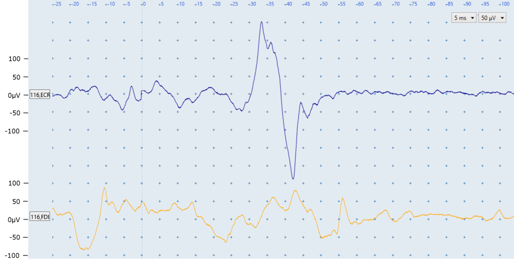
Figure E: The ECR EMG trace (top) displays biological noise because the ECR is activated, particularly before the MEP that is present beginning at ~28ms. This noise can be identified as muscle activation because it does not have a regular pattern. More information about identifying MEPs in the presence of biological noise is provided in module 6.
Muscle activation noise is also present in the FDI EMG trace but no MEP is present.
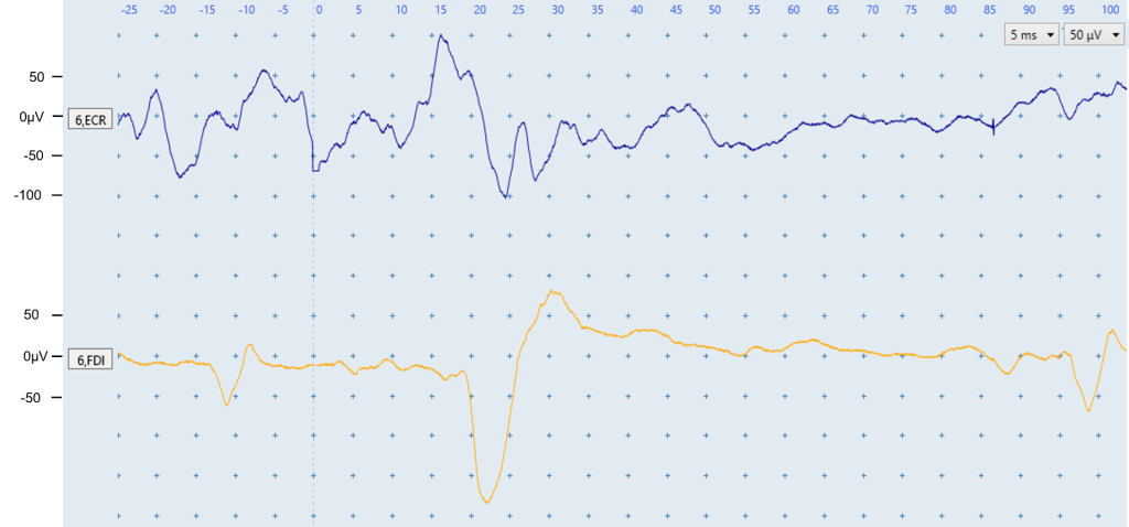
Figure F: The ECR EMG trace (top) displays biological noise which indicates the ECR is activated. The noise in the ECR trace can be identified as muscle activation because it does not have a regular pattern which electrical noise typically does, as seen in the below sections.
A low level of muscle activation is present in the FDI trace, as well as an MEP with a latency of 20 ms. Sporadic motor unit firing can be seen in the fluctuations in the FDI EMG trace at approximately -12 ms and 95 ms. These are identified as motor units firing because of their consistent shape and the latencies do not correspond to the expected FDI MEP latency. Sporadic motor units firing are covered in detail below.
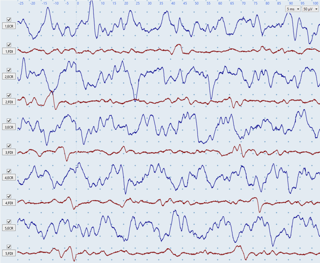
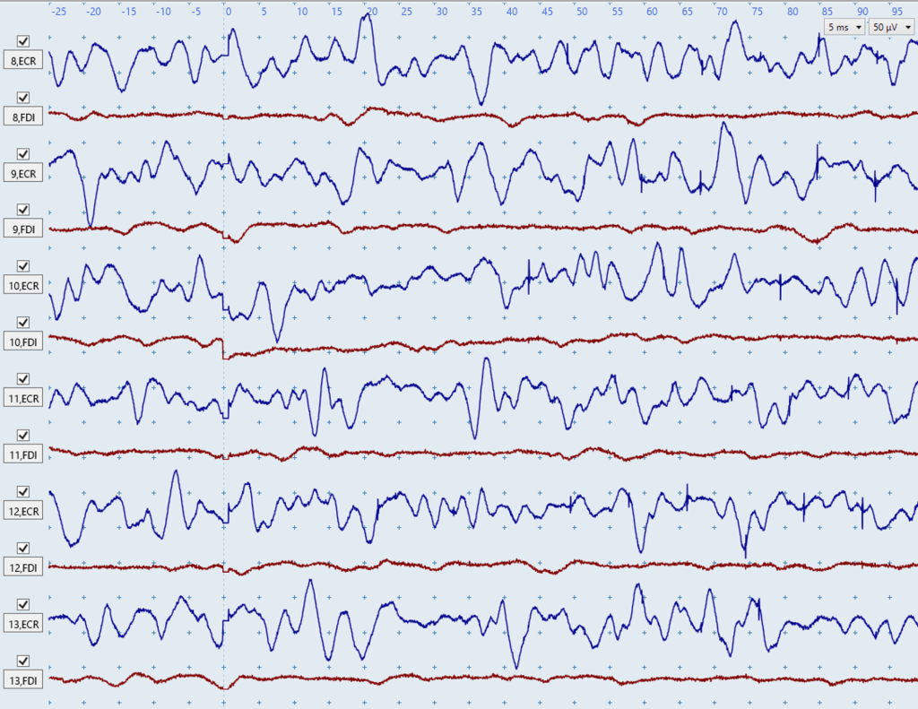
Figures G-H: The two figures above show severe biological noise due to muscle activation in the blue ECR traces. There is low-level biological noise due to muscle activation in the red FDI traces of Figure G, but the red FDI traces in Figure H are largely noise-free. These figures illustrate how biological noise due to muscle activation does not have a consistent shape or rhythm between different traces. No MEPs are present in any trace which you can tell because there are no consistent deflections in the expected MEP latency windows of ~15 – 25 ms for the ECR and ~20 – 30 ms for the FDI.
If you notice muscle activation noise in the EMG traces then try these troubleshooting suggestions to help your patient stay relaxed and at rest:
- Ensure that the patient’s hand and arm are resting relaxed somewhere low like a pillow on their lap or the bed rather than on a table or similar hard elevated surface. Participants resting their hand on an elevated surface like a table will cause shoulder elevation which can lead to muscle activation, particularly in the ECR muscle.
- Pick the patient’s arm up off the pillow, with one hand under their wrist and another hand under their elbow. You can gently move the arm around in space, asking the patient to just relax and give you the full weight of their arm – you can feel whether they relax and let you have the weight. Then just gently drop or place the limb back on the pillow with the instruction to drop their shoulders.
- Say to the patient: Just take a deep breath, let it out, and drop your shoulders.
- Another possible instruction: Imagine you’re relaxing in a spa pool, and your arms are just floating in front of you supported by the warm water.
- Try positioning the patient with the shoulder internally rotated so the forearm is positioned across the front of the body, rather than having the arm pointing straight out in front from the body.
- If muscle activation is occurring in the FDI then trying different hand positions on the pillow is useful particularly, such as having the hand half-open with fingers flexed, rather than resting palm-down with the fingers extended.
- Give the patient a short break from TMS if you have been delivering stimuli for several minutes.
- Make sure the upper limb that is not being recorded from is also at rest. Muscle activity in one upper limb increases activity in the contralateral homologous muscle.
- Slightly vary up the timing between your stimulations so there is approximately 4-6 seconds between stimulations. If you deliver TMS at a regular interval then participants can begin to anticipate being stimulated and tense up.
- If all else fails, you can also try letting the arm hang down at the patient’s side, over the edge of the chair (much harder to do if they are in a bed). This lets the arm just hang under its own weight, but care is needed if the patient has an unstable shoulder.
- If none of this works and you’re still seeing some low level muscle activation noise then you’ll need to just keep going. Sometimes muscle activation decreases over time as the participant relaxes and gets used to the feeling of being stimulated.
Sporadic motor units firing
The second form of biological noise is caused by motor units innervating the ECR and/or FDI firing sporadically. A motor unit is made up of a single motor neuron axon and all of the muscle fibers it innervates. Motor units can sometimes spontaneously fire due to random firing of the motor neuron, but this activity is usually not consciously noticed.
Motor units firing can be identified due to their consistent size and shape in EMG traces. They can appear at any time in the EMG trace and so usually appear at latencies which do not correspond with the expected MEP latency. ECR MEPs have an expected latency of ≈ 15 – 25 ms and FDI MEPs are ≈ 20 – 30 ms. If a motor unit is firing spontaneously then it will often appear more than once in the trace, or at different times between traces.
Re-positioning a patient’s arm and ensuring their arms and hands are fully supported on pillows can prevent or reduce noise from sporadic motor unit firing.

Figure I: The deflections seen in the ECR EMG trace (top) at ~20 ms and ~100 ms are not MEPs. It is important to realize this is a motor unit firing sporadically otherwise the deflection at 20ms may be mistaken as an MEP. You can tell this is a motor unit firing sporadically because of the consistent size and shape of the deflections, and the firing at ~100 ms does not correspond with the expected ECR MEP latency. Re-positioning the patient and ensuring their arms and hands are fully supported on pillows may prevent sporadic motor unit firing. A similar situation can be seen in Figure W below.
No motor units are firing in the FDI trace but a very small MEP can be seen at approximately 33 ms.
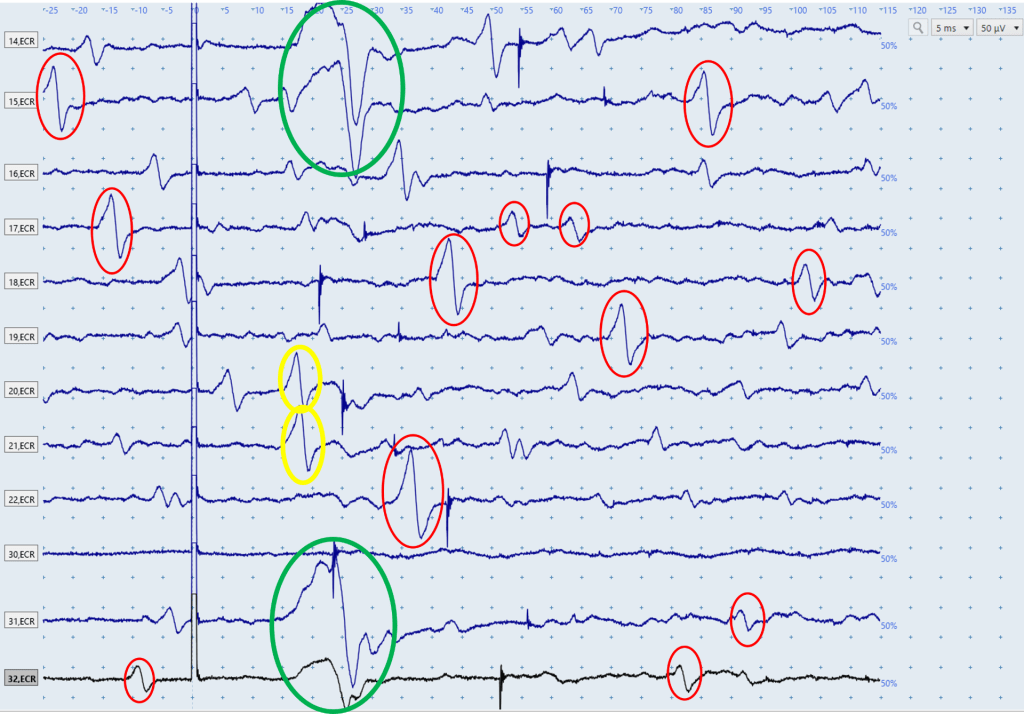
Figure J: The above figure displays a series of ECR EMG traces, each of which is the result of a single stimulation. An ECR MEP is present in the first two and last two traces, and these can be seen in the green circles. Throughout the traces there are a high number of motor units firing, some of which are highlighted in red circles. Although these responses vary in size, their consistent shape and appearance at latencies that don’t correspond to the expected ECR MEP latencies indicates they are motor units firing sporadically. There are many other motor units firing in these traces that haven’t been circled. The two responses in yellow are within the expected window for ECR MEP latencies, however the fact their shape is so similar to the motor units firing, and so dissimilar to the MEPs present in the first and last two traces, indicates they are likely also motor units firing sporadically.
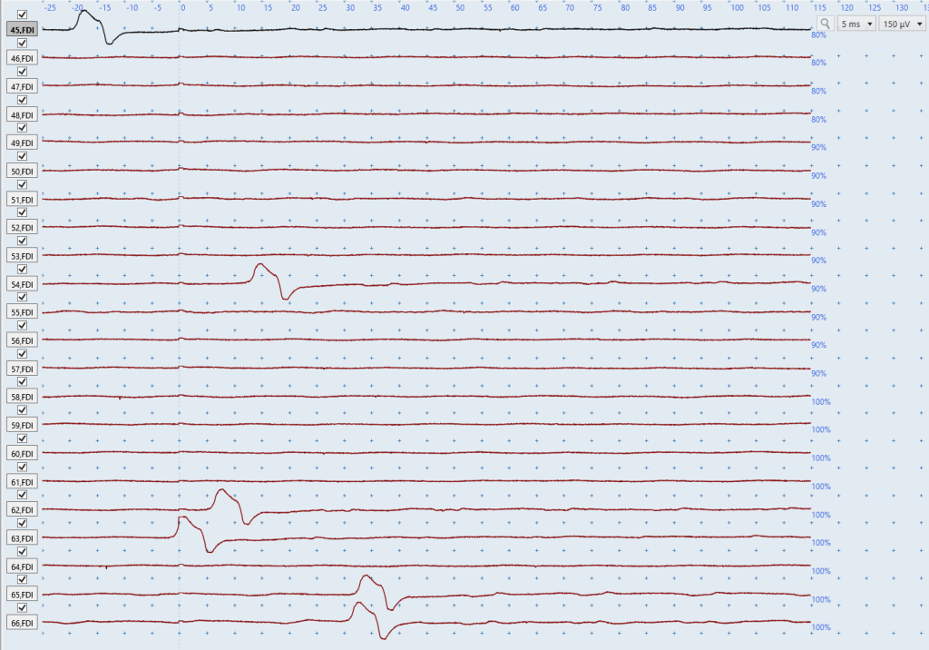
Figure K: You will often need to view a lot of traces at once to determine if a deflection is an MEP or a sporadic motor unit firing. For example, looking at the final two traces in isolation may lead you to think MEPs are present because both deflections have MEP-like shapes, have the same timing, and they occur at ~32ms which is within the expected window for FDI MEPs in a tall participant. However, it is only once you look at the previous recorded traces that you realize the deflections in the final two traces are in fact a motor unit firing spontaneously because of the identical shape of all the deflections.
Non-Biological Noise
You also need to ensure that the EMG traces are free from non-biological sources of noise. The three main sources of non-biological noise are electrical noise in both channels, electrical noise in one channel, and prolonged stimulus artefacts.
Electrical noise
Noise can be generated from electrical sources, such as poor contact between the recording electrodes and patient’s skin, or electrical noise in the room from surrounding electrical equipment.
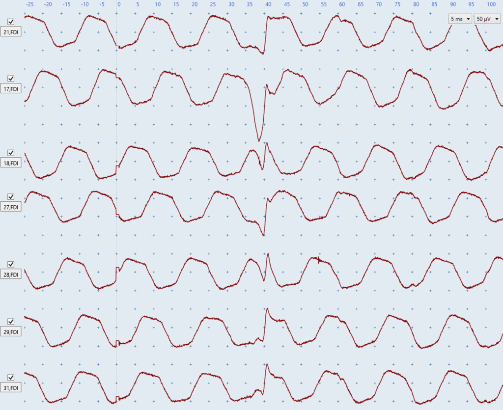
Electrical noise issues are usually characterized by having a regular pattern in the EMG trace, as you can see in the examples below.
It’s also important to recognize that electrical noise issues come in many different shapes and sizes. For example, both rhythmic wave-like patterns and abrupt, sharp deflections in the EMG traces are indicative of electrical noise issues. Although Figures L-S below all show electrical noise issues, almost none of them show the same electrical noise.
Troubleshooting suggestions for electrical noise in both channels include but are not limited to:
- checking the grounding strap/electrode has not lost contact with the skin
- wiping the ground strap with an alcohol wipe if a strap is being
- changing the position of the ground electrode to a different bony prominence
- ensuring the electrode cables are not tangled up with each other
- checking whether anyone is touching the patient or the TMS trolley during the test
- unplugging the bed from its electrical power supply
- turning off fluorescent lighting where possible
- increasing the distance between the TMS stimulator, the EMG box, and the participant.
- plugging the TMS machine into a different power outlet
- checking skin preparation for electrodes was adequate which includes shaving hair, cleaning with alcohol wipes, and lightly abrading using prep tape
- checking the electrodes have not lost contact with the skin. Tape can be used to secure electrodes
- checking electrode cables are firmly attached at the patient and the EMG unit
- if electrical noise only appears during bilateral facilitation it is likely caused by the patient tugging on the electrodes and/or cables. This can be solved by changing the position of the cables or the patient’s upper limbs to ensure the patient performs bilateral facilitation in a way that doesn’t tug on the electrodes and/or cables.
Electrical noise in both channels
Electrical noise present in the traces for both muscles typically indicates an issue with the grounding strap/electrode or the environment. In this situation follow the suggested troubleshooting steps above.

Figure L: Both channels have a regular wave-like pattern that indicates electrical noise is present. As electrical noise is present in both channels there may be issues with EMG set-up for the grounding electrode/strap, or an environmental issue such as interference from a person touching the TMS trolley or patient, fluorescent lighting, or electrical power supply to the bed.
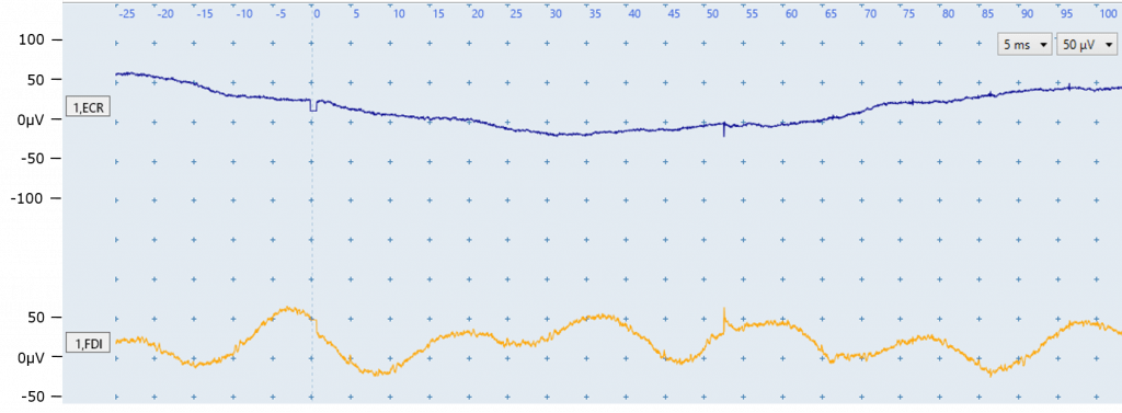
Figure M: Each channel is affected by a different type of electrical noise. The ECR trace (top) has a drifting baseline. The FDI trace has electrical noise with a sine-wave pattern. As electrical noise is present in both channels there may be issues with EMG set-up for the grounding electrode/strap, or an environmental issue such as interference from a person touching the TMS trolley or patient, fluorescent lighting, or electrical power supply to the bed.
 \
\
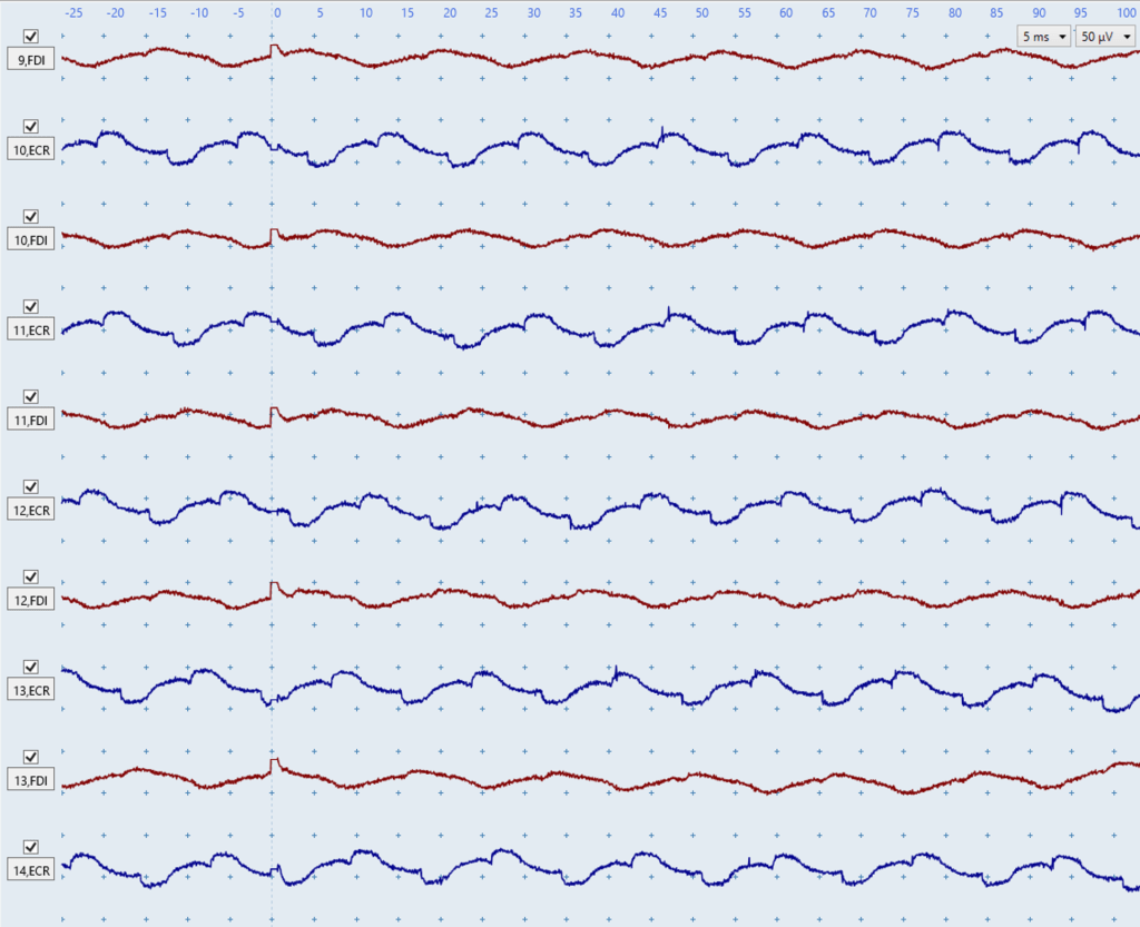
Figure N: The above figure shows a low level of electrical noise present in both the blue ECR traces and the red FDI traces which you can tell by the wave-like patterns. This figure illustrates how electrical noise usually looks very consistent between traces in contrast to biological noise due to muscle activation which does have a consistent shape as seen in Figures G and H above. Even low level electrical noise such as in Figure N could obscure very small MEPs such as those present in Figure C above and lead to an incorrect MEP status determination.
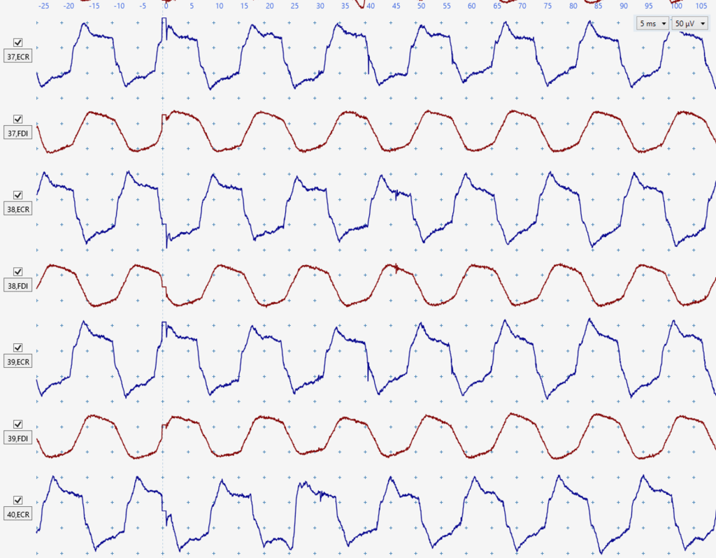
Figure O: Another demonstration of electrical noise looking consistent between traces in both muscles. Electrical noise of this amplitude would definitely obscure small MEPs such as those in Figure C above.
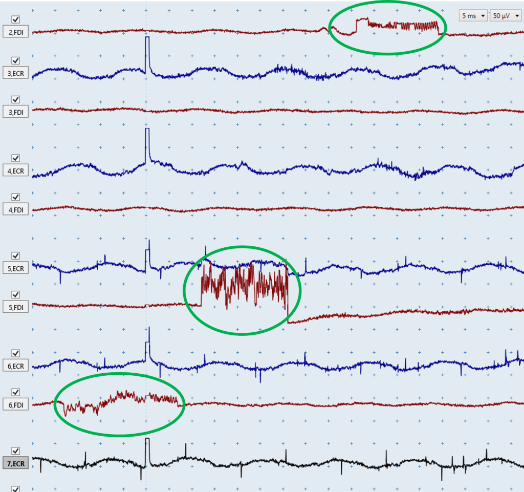
Figure P: The above image shows consistent electrical noise issues in the blue ECR traces. However, the above image also shows that occasionally electrical noise won’t be consistent between traces such as in the green circles. These noise issues can still be identified as electrical because of the very abrupt and non-natural deflections in the EMG traces, and hopefully you can see how different these noise issues look compared to biological noise due to muscle activation in Figures D-H.
Electrical noise in one channel
Electrical noise present in the EMG traces of one muscle suggests the noise issues are specific to the EMG set up for that muscle. The main reasons this happens is because of a loose or faulty cable, poor electrode contact with the skin, or a faulty electrode. When you see electrical noise in one channel swapping the electrode cables between muscles is the quickest way to understand the problem. This will involve unclipping the cables from the electrodes of one muscle and connecting them to the electrodes of the other muscle:
- If the noise is caused by a problem with the cables then the noise issue will remain on the same channel on the screen despite recording from a different muscle. In this situation using a different set of cables should resolve the issue.
- If the noise is caused by a problem with the electrodes then the noise issue will now be on the channel for the other muscle. In this case you will need to remove the electrodes, re-prep the skin areas, and attach new electrodes. If you’re using a MEGA-TMS system, it can identify exactly which EMG electrode has high impedance and is the likely source of noise, so you only need to re-prepare and replace that electrode. Impedance can be checked with the MEGA-TMS system by pressing a button on the top left corner of the EMG unit labelled “electrode test” while the electrodes are attached to the patient.
The diagram below demonstrates how to swap cables between electrodes, and this example uses a MEGA-TMS stimulator and Focus EMG system.
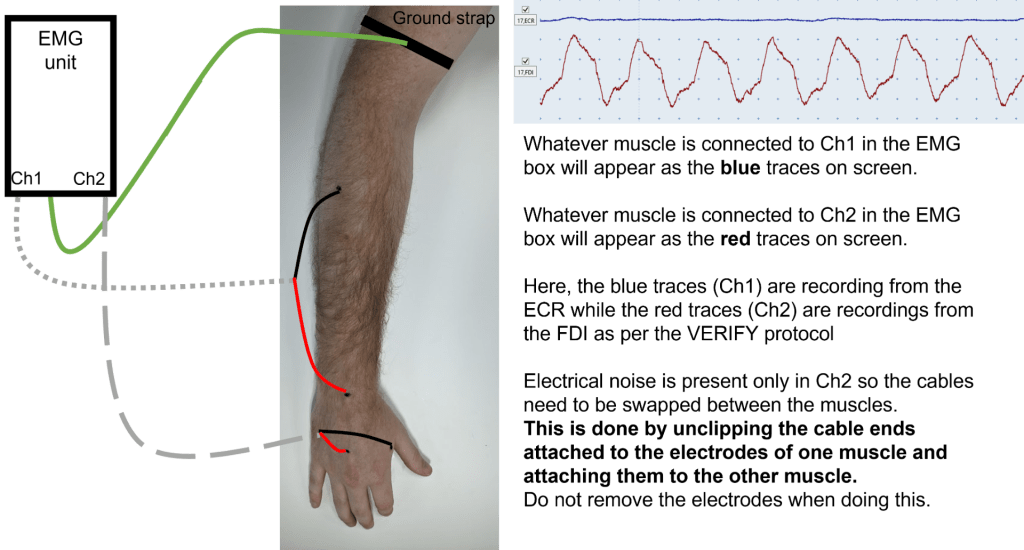
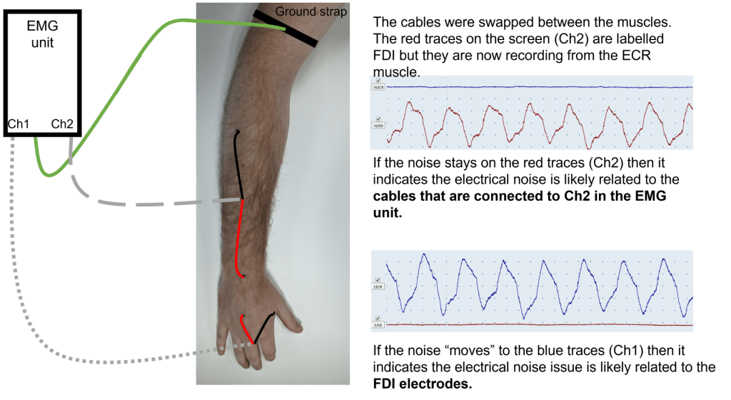

Figure Q: The ECR EMG trace (top) is contaminated by electrical noise, which you can tell based on its regular pattern. As this electrical noise is only present in one channel it suggests that the issue is specific to the EMG set up for the ECR such as a loose cable, or poor electrode conduction due to lack of contact with skin, or a faulty electrode. No noise issues are present in the FDI EMG trace.
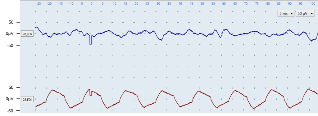
Figure R: The FDI EMG trace (bottom) is contaminated by electrical noise which you can tell by the regular pattern. As this electrical noise is only present in one channel it suggests that the issue is specific to the EMG set up for that muscle such as a loose cable, or poor electrode conduction due to lack of contact with skin, or a faulty electrode.
The ECR EMG trace (top) does not contain electrical noise but does contain biological noise due to muscle activation. You can tell this is muscle activation noise because it does not have a regular pattern as you can see in the FDI.
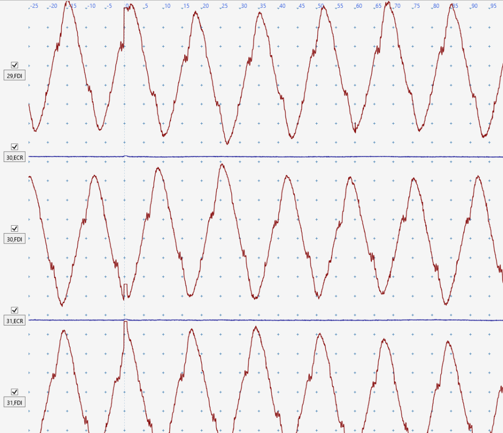
Figure S: The blue ECR traces are perfect and free from noise, however there is very significant electrical noise in the red FDI traces. You can tell this is an electrical noise issue because of the consistent shape both within and between FDI traces. This noise is likely to be caused by a loose cable, poor electrode conduction due to lack of contact with skin, or a faulty electrode. This FDI electrical noise is so severe you’re unlikely to be able to detect any FDI MEPs that may be present.
Prolonged stimulus artefact
The second form of electrical noise is caused by a prolonged stimulus artefact. MEP identification can be difficult if the stimulus artefact of the TMS trigger has a prolonged tail that overlaps with the expected onset of the MEP. The earliest expected MEP onset is from 15 ms after the stimulus for ECR, and from 20 ms after the stimulus for FDI.
The stimulus artefact may be reduced by following the troubleshooting advice for electrical noise issues listed above.
If prolonged stimulus artefacts only appears while the patient is performing bilateral facilitation it is likely caused by the patient tugging on the electrodes and/or cables. This can be solved by changing the position of the cables or the patient’s upper limbs to ensure the patient performs bilateral facilitation in a way that doesn’t tug on the electrodes and/or cables.
It’s important to realize that stimulus artefacts typically only cause issues if they’re prolonged in the x-axis (time), not the y-axis (amplitude). This is seen in Figures V and W below.
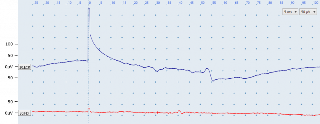
Figure T: There are several points of interest in the above image:
- An elongated stimulus artefact is present in the ECR trace because the ECR trace does not return to baseline until ~20 ms after stimulation. In contrast, the FDI trace returns to baseline a few milliseconds after stimulation as expected. The ECR prolonged stimulus artefact may be reduced by following troubleshooting advice for electrical noise issues.
- The fluctuation seen in the ECR EMG trace at around 50 ms is not a MEP. This is most likely a motor unit firing sporadically because of its appearance at a latency which does not correspond with the expected latency between 15 and 25 ms for ECR MEPs. Re-positioning a patient and ensuring their arms and hands are fully supported on pillows may prevent or reduce sporadic motor unit firing.
- The fluctuation seen in the FDI EMG trace at around 40 ms is also likely not an MEP due to its timing, and is also most likely a motor unit firing sporadically.
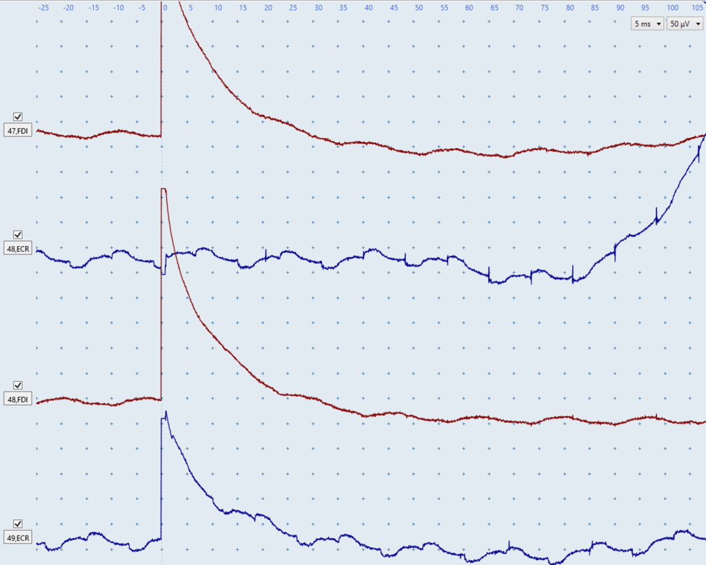
Figure U: The two red FDI traces clearly demonstrate prolonged stimulus artefacts as they only return back to baseline at ~30 ms.
The top blue ECR trace does not have a prolonged stimulus artefact, however an electrical noise issue is present. Additionally, the abrupt upwards deflection of the trace starting at ~85 ms is indicative of an electrical noise issue similar to the abrupt and oddly-shaped deflections in Figure O above.
The bottom blue ECR trace has the same electrical noise issue as the top trace, however it also contains a prolonged stimulus artefact that only returns to baseline at ~25 ms.
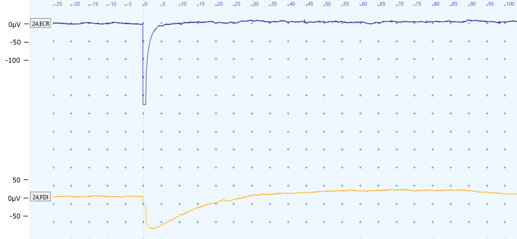
Figure V: A prolonged stimulus artefact is present in the FDI EMG trace (bottom) because it only returns to baseline at approximately 30 ms, which is within the expected onset latency for FDI MEPs. This would be considered a prolonged stimulus artefact.
There is a large deflection in the ECR EMG trace (top) at the point of stimulation 0 ms, however this is not concerning as the EMG trace returns to baseline at approximately 5 ms and is thus unlikely to affect MEP status determination. This would not be considered a prolonged stimulus artefact.
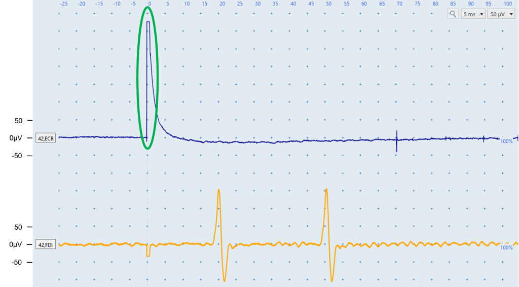
Figure W: The stimulus artefact in the ECR is very large in the y-axis as it reaches an amplitude of ~325 microvolts, however it returns back to baseline by ~8ms so won’t interfere with MEP status determination. This would not be considered a prolonged stimulus artefact.
The yellow FDI trace contains 2 motor units. Although the deflection at ~18 ms is within the expected latency for FDI MEPs, the fact it has an identical shape and amplitude to the deflection at ~48 ms indicates they’re both likely motor units firing. Seeing deflections of similar amplitude and shape at sporadic latencies in other FDI traces would further confirm these are motor units firing. Figure I shows a similar situation of two motor units firing despite one of them being in the appropriate latency range for FDI MEPs.
Resources
EMG Troubleshooting Cheat Sheet
Frequently asked questions
What should I do if I can’t get my patient to relax their arms completely and there is low-level biological noise in the EMG trace?
Follow the troubleshooting suggestions for muscle activation such as repositioning the patient’s arms, reminding them to drop their shoulders, or taking a short break. If these steps don’t help you could try drawing the patient’s attention away from testing procedures, to reduce anxiety and fidgeting associated with testing. You can also start with low intensity stimulation to help the patient get used to TMS, and see if muscle activation reduces over a few minutes. If none of the troubleshooting suggestions work then you will have to continue the TMS session with the biological noise present and determine whether MEPs are present amongst the muscle activation noise. Advice and examples of MEPs in the presence of biological noise due to muscle activation are covered in module 6.
How can I tell if it is a motor unit firing or a real MEP?
Review the latency and shape of the response. If the response is well outside the expected latency window it is very unlikely to be a MEP. If the response is within the expected latency window you need to check to see whether the response is also present at other times in the trace. If a motor unit is firing spontaneously, you will usually see it appear more than once in the trace, and in other traces. Motor unit responses will have a very consistent size and shape, and usually appear more than once in the trace. These two features differentiate them from a MEP, have a more variable size and shape, and will only occur once and within the appropriate time window. Of course, you might see a MEP at the right latency in a trace that also contains motor unit firing. MEP+ classification can be made if a MEP response of an appropriate latency is identified, even if there is also a motor unit firing outside the latency window.
Should I still attempt to complete the test if I we can’t fully resolve all noise issues?
Sometimes MEP status can still be determined despite noise such as in the pictures below. For example, when electrical noise is present in the EMG trace but the size of the MEPs is larger than the noise. In this situation it is important that MEPs are consistently seen in most traces. However before classifying a patient as MEP-, all efforts must have been made to elicit a MEP if possible. This means that EMG needs to be noise-free, in particular within the expected latency window. If you cannot elicit MEPs in a patient and noise can’t be reduced at the time of testing then seeking the opinion of another TMS operator to troubleshoot may be useful, or it may be necessary to reschedule another TMS session. You could repeat the test in a different clinical environment if electrical noise was thought to contribute to noise issues.

Quiz
Click here for a quiz to assess your learning on EMG Technique.
Once the practice quiz has been completed with at least 70% correct you will be emailed a link to the final quiz for this module.
If you pass the final quiz with at least 80% correct you will be emailed a certificate of completion for the EMG Technique module. There is no limit to the number of attempts for the practice or final quiz.
Please email verify.study.tms@gmail.com if you have any questions or comments.
